


.jpg)
.JPG)
- 光模塊
-
SFP光模塊
SFP+光模塊
XFP光模塊
AOC有源光纜
QSFP+光模塊
QSFP28光模塊
SFP28光模塊
1×9光模塊
射頻光模塊 - 工業(yè)交換機(jī)
-
工業(yè)級光纖收發(fā)器
導(dǎo)軌式非網(wǎng)管型交換機(jī)
導(dǎo)軌式網(wǎng)管型交換機(jī)
機(jī)架式非網(wǎng)管型交換機(jī)
機(jī)架式網(wǎng)管型交換機(jī)
工業(yè)級三層交換機(jī)
電力行業(yè)工業(yè)交換機(jī)
工業(yè)級串口服務(wù)器 - 光纖收發(fā)器
-
10/100M光纖收發(fā)器
10/100/1000M光纖收發(fā)器
10G光纖收發(fā)器
萬兆光纖放大中繼器 - 寬溫以太網(wǎng)交換機(jī)
-
非網(wǎng)管交換機(jī)
智能撥碼交換機(jī)
智能撥碼POE交換機(jī)
二層網(wǎng)管交換機(jī)
二層網(wǎng)管POE交換機(jī)
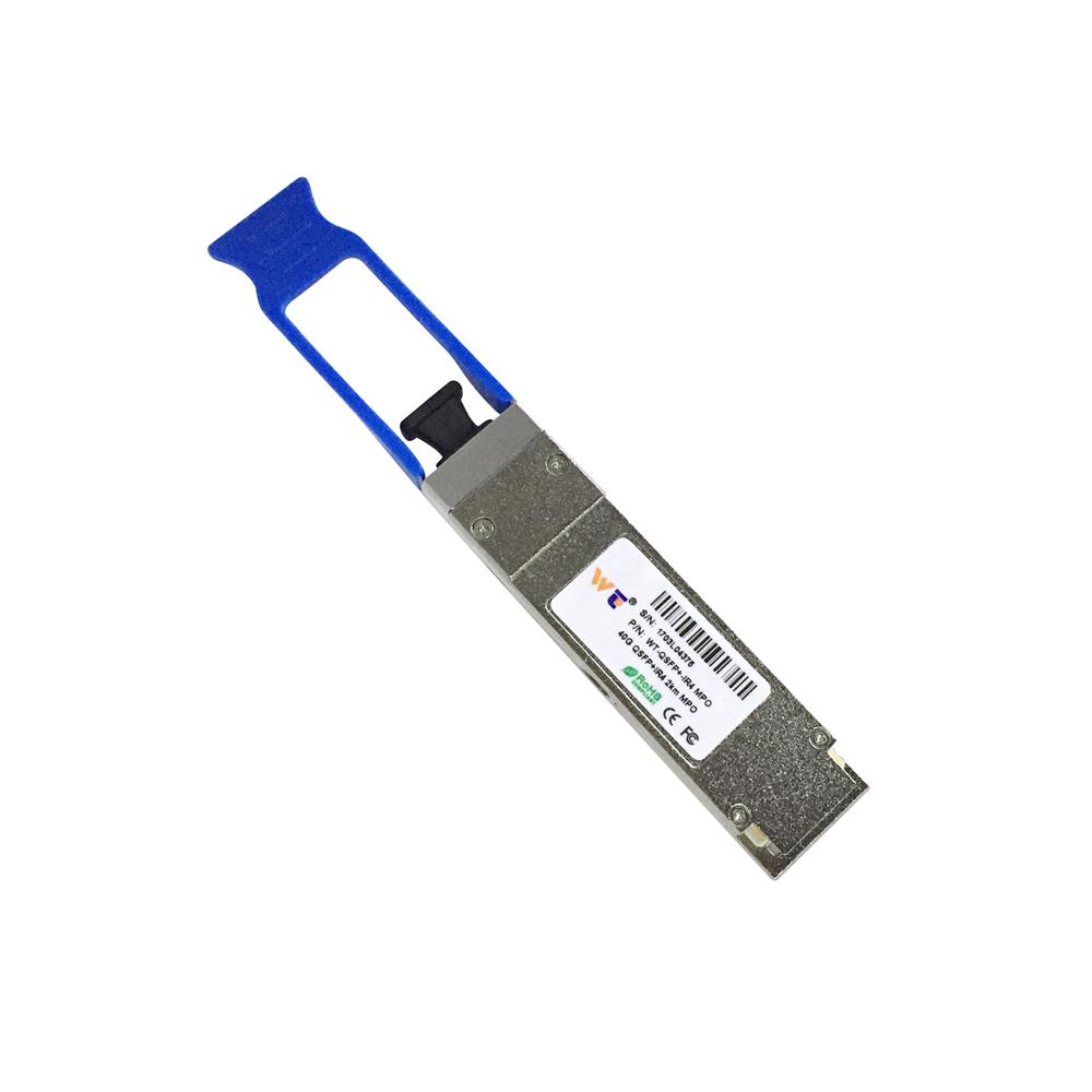


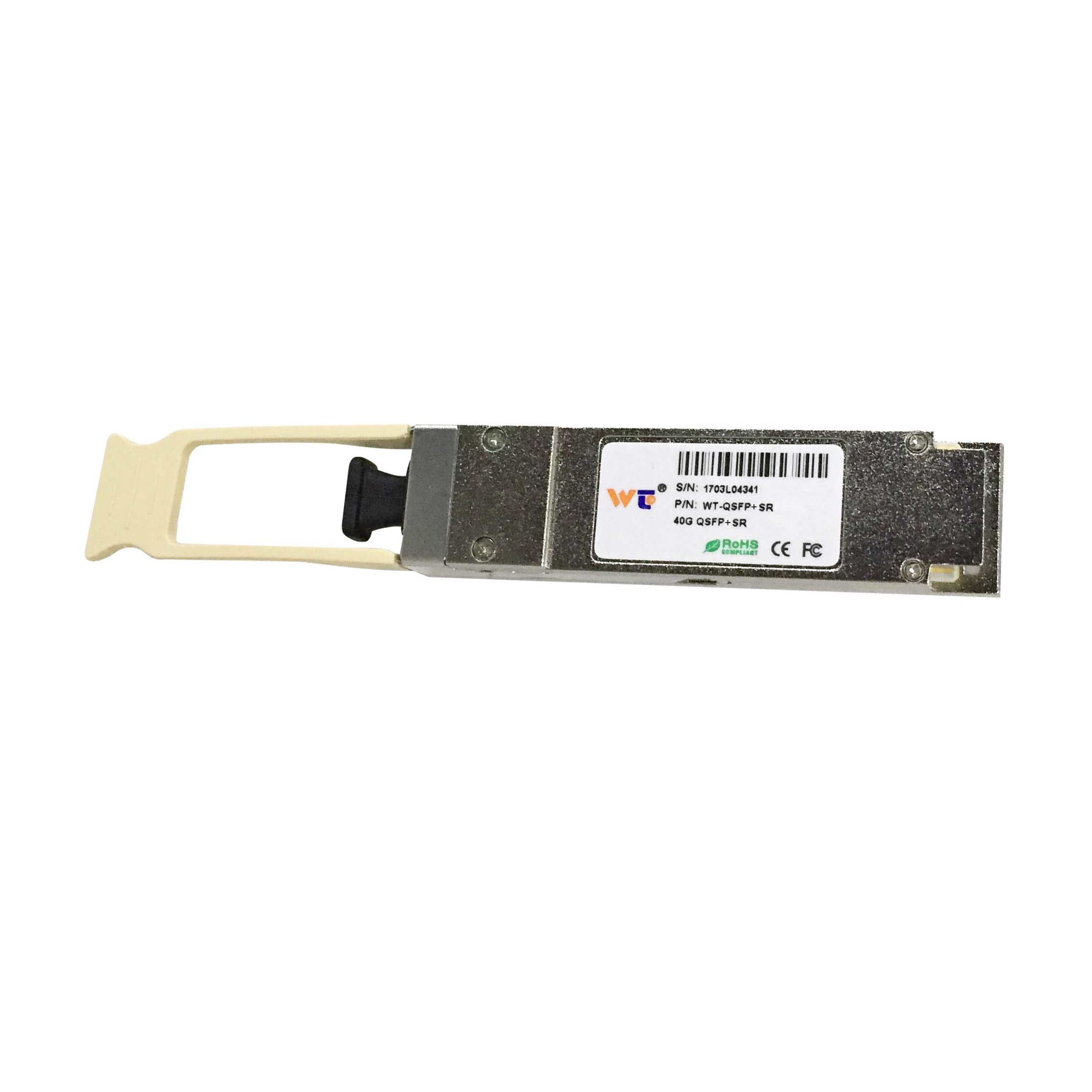
FEATURES
lFour-channel full-duplex transceiver modules
lTransmission data rate up to 11.2Gbit/s per channel
lUp to 2km transmission of single mode fiber
lLow power consumption <2.5W,meet class 3
lOperating case temperature 0°C to +70°C
l3.3V power supply voltage
lRoHS 6 compliant
lHot Pluggable QSFP form factor
lSingle MPO connector receptacle
lBuilt-in digital diagnostic function
APPLICATIONS
lInfiniBand QDR, DDR and SDR
l40G Ethernet
lProprietary High Speed Interconnections
lData center
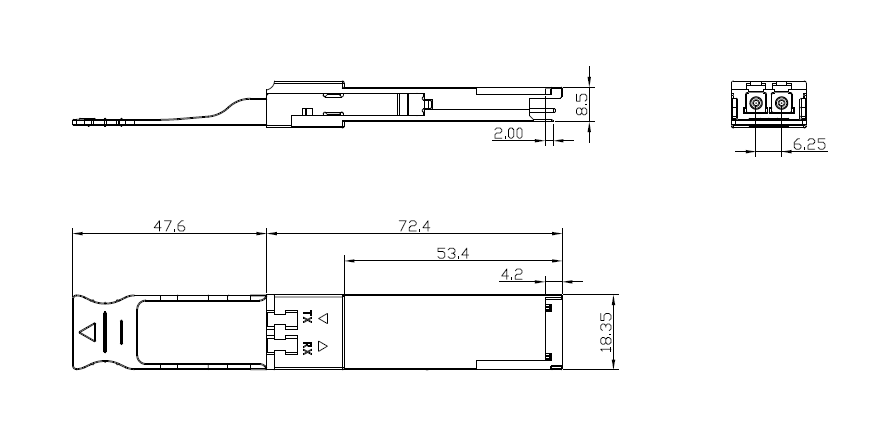
Mechanical Dimensions
Optical Characteristics
All parameters are specified under the recommended operating conditions with PRBS31 data pattern unless otherwise specified.
|
Parameter |
Symbol |
Min |
Typical |
Max |
Unit |
Notes |
||
|
Transmitter |
||||||||
|
Center Wavelength |
λC |
1270 |
1310 |
1350 |
nm |
1 |
||
|
RMS Spectral Width |
λrms |
- |
|
3.5 |
nm |
1 |
||
|
Average Launch Power, each lane |
PAVG |
-5.2 |
-0.5 |
+1.0 |
dBm |
|
||
|
Optical Modulation Amplitude (OMA) |
POMA |
-4.5 |
-0.5 |
+2.0 |
dBm |
1 |
||
|
Difference in Launch Power between any two lanes |
Ptx,diff |
|
|
5.0 |
dB |
|
||
|
Launch Power in OMA minus Transmitter and Dispersion Penalty (TDP), each Lane |
OMA-TDP |
-9.7 |
- |
|
dBm |
1 |
||
|
Rise/Fall Time |
Tr/Tf |
|
|
50 |
ps |
|
||
|
Extinction Ratio |
ER |
3.5 |
|
|
dB |
|
||
|
Relative Intensity Noise |
Rin |
|
|
-128 |
dB/Hz |
|
||
|
Optical Return Loss Tolerance |
TOL |
|
|
12 |
dB |
|
||
|
Transmitter Reflectance |
RT |
|
|
-12 |
dB |
|
||
|
Transmitter Eye Mask Margin |
EMM |
10 |
|
|
% |
2 |
||
|
Average Launch Power OFF Transmitter, each Lane |
Poff |
|
|
-30 |
dBm |
|
||
|
Transmitter Eye Mask Definition {X1, X2, X3, Y1, Y2, Y3} |
|
|
|
|
|
|||
|
Parameter |
Symbol |
Min |
Typical |
Max |
Unit |
Notes |
|
Receiver |
||||||
|
Center Wavelength |
λC |
1270 |
1310 |
1350 |
nm |
|
|
Damage Threshold |
THd |
+3 |
|
|
dBm |
|
|
Overload, each lane |
OVL |
+1 |
|
|
dBm |
|
|
Receiver Sensitivity in OMA, each Lane |
SEN |
|
|
-12.5 |
dBm |
|
|
Difference in Receive Power between any two Lanes (OMA) |
Prx,diff |
|
|
5.0 |
dB |
|
|
Signal Loss Assert Threshold |
LOSA |
-30 |
|
|
dBm |
|
|
Signal Loss Deassert Threshold |
LOSD |
|
|
-15 |
dBm |
|
|
LOS Hysteresis |
LOSH |
0.5 |
|
6 |
dB |
|
|
Optical Return Loss |
ORL |
|
|
-12 |
dBm |
|
|
Receive Electrical 3 dB upper Cutoff Frequency, each Lane |
Fc |
|
|
12 |
GHz |
|
Notes:
1. Transmitter wavelength, RMS spectral width and power need to meet the OMA minus TDP specs to guarantee link performance.
2. The eye diagram is tested with 1000 waveform.
有關(guān)詳細(xì)信息,請?jiān)?ldquo;相關(guān)下載”中查看數(shù)據(jù)表.